On a Roll: Revealing the Final Design of the Wheelchair Hill Assist
- Nov 25, 2023
- 4 min read
Team RLNT< here with another project update on our Wheelchair Hill Assist Device. For those of you in need of a reminder: we are developing a Wheelchair Hill Assist Device aimed to reduce the energy expenditure of individuals navigating wheelchair ramps by a minimum of 50%. The device user will complete the following steps to use the device:

Since our last post, we have made considerable advances in the progress of our device and have completed the following tasks:
Completed Tasks:
Task 4.1 - Finalize the material of the device shell and select fasteners.
The team has selected ASA as the shell's material and has selected 1/4" - 28 x 3/4" socket screws for the lid and 3/8" - 22 x 3/4" socket screws to attach the wheelie bars inserts to the shell. The wheelie bar inserts will be fastened to the wheelie bars with a 1/4" x 1 1/4" thumb screw and wingnut for ease of attachability. This can be seen in Figure 1 below.

Figure 1: Plan of attachment of the device to the wheelchair's wheelie bar.
Task 4.2 - Use the power of the motor and battery voltage/charge to select the motor hub.
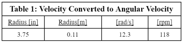
The team team selected a 350[W] 36[V] motor hub with a radius of 3.75 [in].
Task 4.3 - Re-evaluate analyses in Milestone 3 to confirm that the design satisfies the parameters.
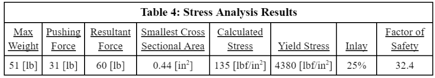
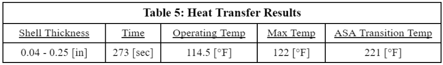
Team RLNT< re-evaluated the stress, heat transfer, static force, and dynamic analyses to ensure that the mechanical and electronic components selected will withstand the project constraints. These key analytical results demonstrate the successes and strengths of the Team's current design. These results can be found in Tables 1-5 below.


Task 4.4 - Evaluate and finalize device installation methods
The team considered 3 arm attachment options shown in Figure 2. Each of these designs would need to be adjustable for multiple wheelchairs. The leftmost design features three separate 3D-printed arm pieces that attach together by threading at each ball joint. The middle design features one rigid-bodied 3D-printed arm. The rightmost design is a metal pin-style adjustable arm, similar to what is found on crutches. These three arm design considerations were compared below in Table 6 to determine the best fit for the design.
Team RLNT< determined that the cost per unit, fabrication, and adjustability are the most important design considerations in selecting the device’s arm style. In this table, fabrication includes both manufacturing time and ease. Cost per unit was weighted heavily since the team wants to make the device affordable for disabled individuals. Fabrication was weighted heavily since the team has less than two months to procure and assemble the device in Capstone 2. Adjustability was weighted heavily since the team has efforts to make the device universal. The weight of the arms was allocated the lowest percentage due to the electrical components weighing less than originally anticipated. 3D printing 3 separate arms in 3 pieces was found to meet the team’s design priorities the best.

Figure 2: Possible arm attachment designs

Task 4.5 - Model CAD of wheelchair hill assist device shell, electronics, and assembly.
CAD models of the final design can be seen below in Figure 3 and Figure 4. Figure 5 features an exploded view of the entire device assembly with a corresponding parts list in Table 7
The shell is designed to house the battery and controller module. A gasket will be used in between the lid and the shell to ensure IP65 rating. The shell will also have built-on legs for the motor hub to be easily attached to the device. Slots will be printed on the legs to ensure the hub slides onto the legs. Using the maximum height of the wheelie bars, the team designed the wheelie bar attachments to be located exactly 10 inches off the ground. This is to decrease the need for three-dimensional attachments for one of the designs. Two of the wheelchairs will require drop bars to meet the 4.5 and 5-inch heights. ¼ x ¾ inch fasteners were selected to hold the shell lid in place. A fine pitch was selected for more gripping strength to ensure the gasket has proper compression for ingress protection. ⅜ x ¾ inch fasteners were selected to fasten the wheelie bar attachments to the shell to increase the strength of the wheelie bar attachments. The wheelie bar attachments were also printed with a ball joint that will allow a tap to create a 1” screw thread to screw in on one side, and the bar part of the attachment is printed at 1” and will have a tap used on it to screw into the ball joint.
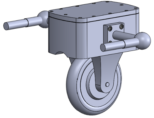
Figure 3: CAD of the final design solution.

Figure 4: CAD of final design solution with wheelie bar.

Task 4.6 - Create a Bill of Material (BoM) for the device.
Team RLNT< has sourced all of the required materials and is prepared to begin ordering supplies at the beginning of Capstone 2.
Task 4.7 - Create standard operating procedures (SOP) for device assembly.
A basic SOP has been generated based on the knowledge of the project to this point. Photos of the physical device will be added to the document in Capstone 2.
In Progress Tasks:
Task 4.8 - Submit critical design review to finalize the design of the device.
Team RLNT< has completed their CDR presentation and is currently in progress of writing their final design review report.
Looking forward to Capstone 2, Team RLNT< has completed all of their proposed steps in order to be ready to execute their design including defining the scope of the project, evaluating the constraints of the preliminary design, analyzing the parameters of the device, and finalizing the design of the wheelchair hill assist device.
Stay tuned for more exciting updates as the team continues to advance the project! As always, thank you for your constant support.


Comments